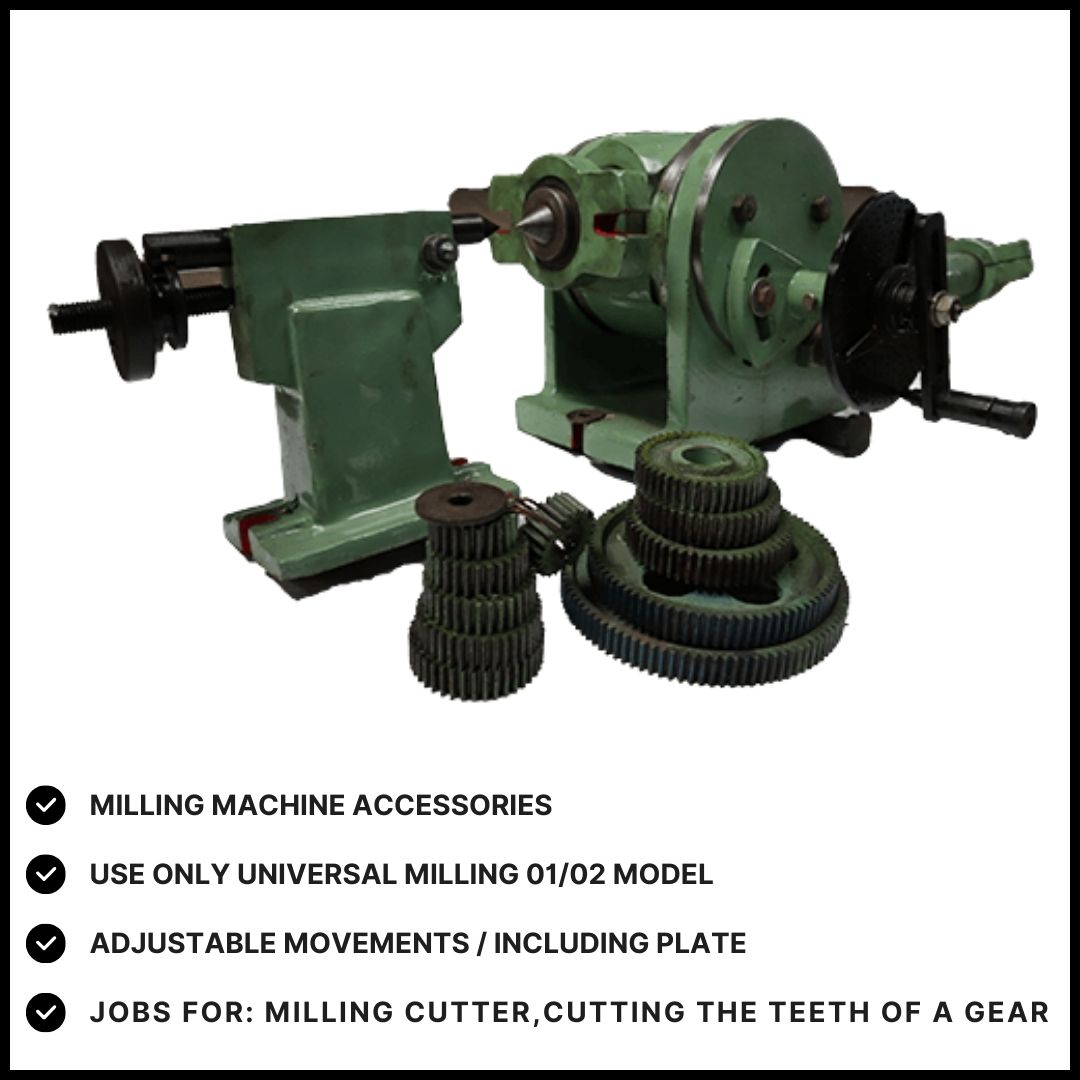
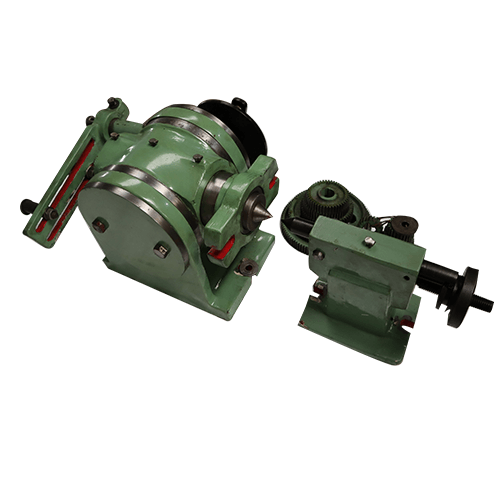
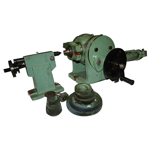
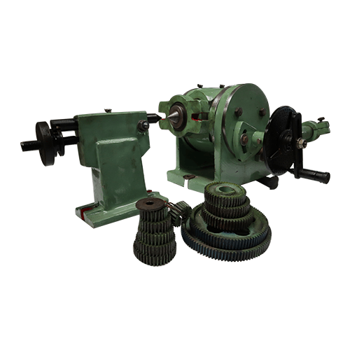
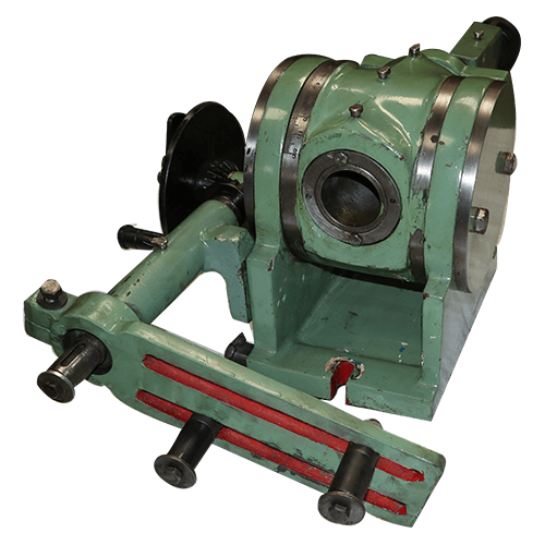
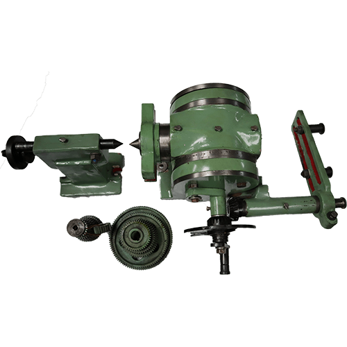
Dividing head or indexing head is a special work holding device, which is bolted on the machine table. The work may be mounted on a chuck fitted on the dividing head spindle or may e supported between a live and dead center. The dead center is mounted on a foot stock as in a lathe tail stock that is bolted on the machine table after correctly aligning its spindle axis with the dividing head spindle. The attachment is principally used for dividing the periphery f a work piece in equal number of divisions for machining equally spaced slots, or grooves. The worm and worm gear driving mechanism of the attachment can be linked with the table lead screw for cutting equally spaced helical grooves on the periphery of a cylindrical work piece.
Key Uses:
- Gear Cutting: By dividing the workpiece into equal segments, you can cut teeth on gears with accurate spacing and profiles. The dividing head allows you to rotate the workpiece incrementally to achieve the precise tooth spacing required.
- Indexing: For tasks that require machining multiple equally spaced features, such as holes around a circle, the dividing head can be set to index the workpiece to specific angles. This is useful for making patterns or arrays of holes.
- Angled Milling: It enables milling at specific angles relative to the workpiece’s axis. For instance, if you need to mill a slot or a feature at a 45-degree angle, the dividing head can position the workpiece accordingly.
- Complex Shaping: By combining rotation with movement, you can create complex shapes and contours that would be difficult or impossible to achieve with just the milling machine’s table movements.
Key Components:
- Spindle: Holds the workpiece and rotates it. It usually has a chuck or other fixture to secure the workpiece.
- Index Plates: These plates are used to divide the rotation into equal parts. By selecting different plates or settings, you can achieve different divisions, like 10, 20, 30, etc.
- Gear Train: A series of gears inside the dividing head that determines the rotation of the spindle based on the input settings. It translates the operator’s settings into precise rotations.
- Tailstock: Often used to support longer workpieces and provide additional stability during milling.
- Graduated Dial: Allows for precise setting of angles and positions. The dial typically has a scale that helps you make fine adjustments.
Basic Operation:
- Setup: Mount the dividing head onto the milling machine’s table. Secure the workpiece in the spindle or chuck.
- Indexing: Use the index plates or gears to set the desired number of divisions. This will determine how far the workpiece will rotate for each indexing operation.
- Milling: Position the milling cutter and adjust the workpiece to the correct angle or position. Begin milling according to your project requirements.
- Adjustments: Make any necessary adjustments to the angle or position as you work. This may involve recalibrating the dividing head or changing settings.